Friday 9 November 2012

Off-side Panel

With the engine in place, the next job is fitting of the side panels before final fit of the front suspension.
As I had chosen to fit the back panel first, I knew that the side panels would probably not be a perfect fit where they meet the back panel at the rear wheels. A couple of minutes with the shears soon solved this. 
To fix the side panels I have elected to only use rivets on the underside of the panel - where they can't be seen. Where the chassis meets the panel I have used "black glue". I am really impressed by this stuff and don't believe the panel will move at all once it is cured. Seen in the photo on the right is the first stage of the process. I will bend and fix the rear portion after freeing the clamps from the front, once it has dried.


Engine - Part 4

GBS kindly sent the missing spacers and bolts via first class post. 36 hours later they turned up :-( Not GBS to blame, but our postal service which seems to be in steep decline..... but enough of that.

With the spacers and bolts supplied I bolted the engine mounts to the engine block and lowered the engine so that it just rested on the chassis but carried no weight. I had already mated the engine and gearbox and bolted them together once more. 
The final step is to centre the engine in the chassis by marking the mid-point on a chassis cross member and aligning it with the centre of the nut on the flywheel. The position of the holes on the chassis plates for the engine mounting brackets was then marked and drilled to 8mm. 
I found that one of the off-side bolts would have been too close to the chassis to get a nut on underneath so I drilled a new hole in the bracket and used that instead. My logic being that the slight weakening of the plate by drilling another hole was much less of an issue than leaving one bolt off altogether.
As the engine can be hoisted vertically using this method of installation it was simple to move it out of the way to drill the plates. 
With the chassis plates drilled, it was now time to finally fit the engine and gearbox and torque up the bolts on the gearbox mount, prop shaft, gearbox casing and engine mounts (see Torque Settings). Finally with the side panels still off I fitted the started motor. Not the simple 5 minute job I thought. The top bolt is too close to the gearbox housing to tighten properly. After a few minutes filing down the rim of the nut head, it went in.

Wednesday 7 November 2012

Engine - Part 3

Beautiful sunrise this morning.


I spoke to the guys at GBS yesterday about how to install an engine and gearbox on my own. There are two methods. The first is to mate the engine and gearbox and fit both as a single unit. This is difficult on your own but not impossible. The difficulty is the weight of the combined unit and manoeuvring it into the chassis opening whilst it dangles from the crane. The second is to fit them separately: the gearbox first and then the engine. The latter is simpler on your own because the gearbox can be positioned manually and the engine can go in almost vertically on the hoist. 
I decided to fit them separately.
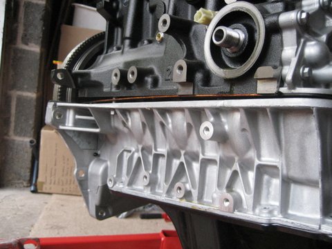
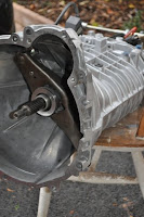
First I needed to remove some gearbox casing from the base and bottom corner, and check that the clutch is aligned properly after fitting the spigot bearing. To do this I fitted the two spacers to the gearbox casing and mated the engine and gearbox, bolting it together so that it can be lifted as a single item. The engine spline slid straight into the gearbox and spigot without problem. With the unit dangling on my crane I marked the areas of the casing that needed to be removed. 
After a few minutes with my 9 inch angle grinder, both areas had been removed.
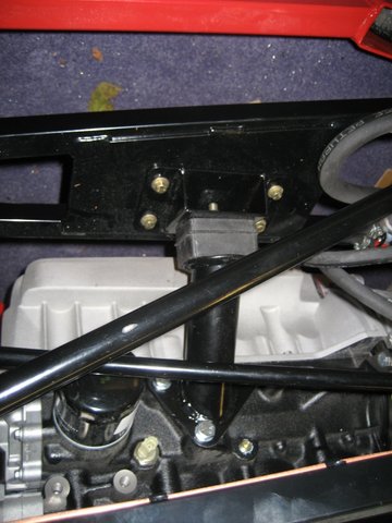
Next the gearbox mount must first be fitted. It requires a little reshaping first of all, followed by drilling the new mounting holes to 8mm. It is then installed from below - fully tightened and thread-locked.
With the gearbox lifted from underneath with my trolley jack, I eased it into place on the mounting and finger tightened the 3 bolts to the prop shaft.
Now the gearbox is in place (approximately) the engine can be dropped in from above vertically.  Having already ensured that the gearbox and engine go together easily, it didn't take long to drop the engine in and mate it with the gearbox once more. Quite straight forward really. Then I found the problem. I didn't have the fixing kit that connects the engine mounts either to the engine or the chassis plates. It was all going so well. As Newark is a 3 hour round trip, I called GBS and they kindly agreed to put the packs in the first class post - maybe tomorrow........


Monday 5 November 2012

Engine - Part 2

With the new sump assembled and ready, it was time to take the old one off - not that it had ever been used. First - drop the oil. As the temperature was only 4 degrees today it took a while. I thought about saving it for re-use, but it has been in there since 2004 so thought better of it. The filter took a bit of time to remove as its rubber seal had stuck to the engine block. 
Removing the bolts holding the sump to the engine block is the not the whole story. Whilst these bolts form the uniform pressure across the gasket, in order to remove the sump there are 2 more bolts that need removing. These are only accessible if you remove the steel tray at the base of the sump. They hold the oil feeder pipe in position. Another thing I learned (the hard way - laying under an oil dripping engine block) was that these bolts have star and not hex heads.

With the old sump finally off, I cleaned the sealant from the engine block and added new sealant to the outside rim of the new sump between the gasket and the edge of the machined surface. This should give that extra bit of protection. I then used a trolly jack to offer up the new sump to the block and bolted back in place.

Gearbox Prep

There are a few jobs that need doing to the gearbox before it is fitted to the engine block. 

Firstly the pin to which the clutch actuator arm connects, needs to be replaced with the longer one supplied by GBS. This is a very simple procedure of knocking out the old one from the rear and tapping the new home into place with a wooden drift.
Next there is the fitting of the quick shift gear lever. Again a simple job. The linkage is held together by pin secured by a rubber washer and the mounting bracket by bolts to the gearbox housing (torgued to 45nm and threadlocked). Just need to make sure that the collar on the universal joint is adjusted so that all gears can be selected before everything is tightened up.

Raceline sump

 The Raceline sump was a real pleasure to assemble. For a third party after-market product it is an extremely well made piece of engineering, even down to the flexible gasket which fits into a machined recess around the top.
This is one of the only assembly jobs on the  build so far where instructions are supplied. The trickiest bit is inserting the oil feed pipe once the rubber washers are in place. It is a really tight fit and difficult to push home. Other than that, the unit goes together very well. Here it is complete and semi wrapped before being put on one side awaiting its bolting to the engine block.

Spigot Bearing

In order to run a transverse engine in-line, a spigot bearing is required to be installed. To do this the clutch pressure plate and clutch need to be removed, before installing the bearing. The bearing needs to be tapped into place with a hammer and a wooden drift making sure that the finger bearings are at the back. Then re-install the clutch and pressure plates making sure the clutch plate is aligned properly.
Forget this small bearing and your gearbox is scrap within a few hours on the road.

Engine - Part 1

Now it's time to start the mods to the Zetec. The first few minor jobs are the removal of the inlet and outlet manifolds in preparation for the install of the GBS units.
First to be removed was the fuel injectors and fuel rail, followed by the manifold itself. 


You can see in the photo the cut-down manifold from GBS at the bottom of this picture. They have a jig to cut down the original inlet manifold to this size. I will return the old/full manifold back to GBS this week when I go up for a quick visit. I want to talk through the engine install before I start in earnest.

Each of the gaskets has to be transferred to the GBS cut-down version before it is installed once more along with the fuel rail and injectors.
The IAVC is also mounted on the old manifold. I have decided to remove it and try and use it with the Emerald ECU and the GBS prototype I purchased from Richard Lincoln. Richard originally bought it from GBS, but then decided to design and build his own. I am not going to do anything with it at the moment but will keep it ready for install when the time comes.

Here is the engine with the new manifold installed. I have taped up the inlets to prevent anything getting in there that shouldn't.
Finally, the exhaust manifold needs to be removed. I am not sure if GBS can recycle this in a similar way to the inlet manifold. I will take it up with me and find out. The heat shield can be re-used along with all of the fixings. Again I have taped the port openings. This photo also shows the installed GBS breather blanking plate which replaces the Ford breather unit.