Not much time today - and minus 3 this morning, so garage time is limited.
The washer bottle is simple job that I have been meaning to do before the engine bay became too cluttered. Ideally this can be done before the engine goes in and when there is plenty of space to swing a drill. I have mounted it on the passenger bulk head with a couple of rivnuts, slightly elevated from the floor pan to allow the water feed to loop underneath. I have also pinned the water pipe with a couple of P-clips.
 I also wired up the heavy duty cables from the starter motor to the alternator and engine ground making sure that the powder coat was removed from the chassis for a good electrical connection. As with the washer bottle, this job is easier to do earlier in the build process as it gets fiddly in a cluttered engine compartment especially the alternator connector which is situated directly under the plenam :-(.
 My last job for today is the plenam install. On visiting the GBS factory a few weeks ago, Simon@GBS gave me the tip that the powder coated plenam chamber needs a little "black glue" to seal it to the cut down mounting plate. This prevents the plenam drawing in air through the sides of the plenam rather than through the throttle.
Before I could do this, the fuel rail needs to be removed and the lugs that remain in the block.
My last job for today is the plenam install. On visiting the GBS factory a few weeks ago, Simon@GBS gave me the tip that the powder coated plenam chamber needs a little "black glue" to seal it to the cut down mounting plate. This prevents the plenam drawing in air through the sides of the plenam rather than through the throttle.
Before I could do this, the fuel rail needs to be removed and the lugs that remain in the block.
 The plenam chamber and cut down fuel injector housing, then bolts into the block.
The throttle from the original manifold then fits to the end of the plenam and the air filter onto the end of that.
Before the scuttle and dash go in, I wanted to run the loom around the engine bay. I am using the GBS loom so it should be quite straight forward - assuming you understand the labels on the loom.
The first (and simplest is the connector to the coli pack - it can't fit anywhere else, but you do need to remove the coil pack to fit it as it is so close to the water rail elbow.

The next one took a little detective work. TPS is obviously throttle position sensor, but the connector on the GBS loom doesn't match the connector on the throttle. Then I found the adaptor cable.
The Crank sensor was a guess. I think it goes here.
To be honest I am not sure what this one is, but it is likely to plug in here. I can't be absolutely certain but my reference photos suggest this to be the case and there are no other connectors of this type within reach of the cable.
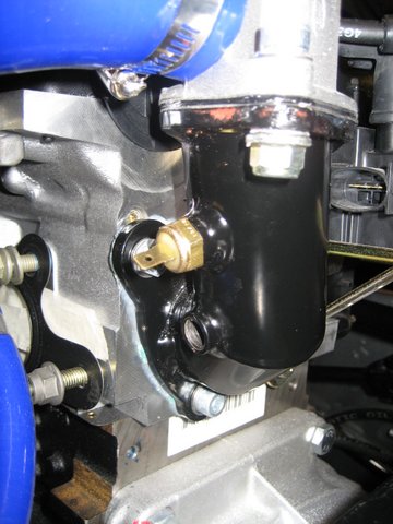
Here are the oil sensors. The top one is for the Smiths oil gauge and the lower one is the standard Ford sensor for the oil warning light.
After opening the Emerald ECU box I discovered two more sensors - lucky because I was short of 2. One is the water temp sensor for the ECU and the other the air temp sensor that fits in the plenham. But which one is which? I googled the part number on one to find it was the air sensor (the one on the right), which meant that the one on the right must be the water sensor. Eat your heart out Sherlock.
Here is the water sensor in place on the water rail elbow.
Here is the air sensor in place on the plenam.
I have no idea what this sensor is. It was already attached to the block, but I don't seem to have a connection for it as part of the GBS loom. Can anyone help?
I spoke to GBS about the radiator fan installation. They don't bother with any brackets to hold the fan to the radiator. They simply clip it to the front and tell me it shouldn't work loose. I am a little dubious. The suspension on a zero is firm and our roads are full of potholes.
 Coincidently I received an email from an other RhoCar member who has been following this blog. He very helpfully pointed out that I had mounted the radiator to the chassis brackets using the radiator mounting brackets on the back of the radiator. Whilst this seemed logical since the holes all lined up, it turns out that the nose cone will not fit if you do this. Instead you need to use the front radiator brackets which means bending over the back ones. The radiator then fits between the chassis brackets rather that in front of them. This meant that I needed to re-size the water rails to fit, but I would rather do that now then when I come to fit the nose cone - many thanks Busby.
While I was fiddling with the radiator I decided to make a couple of small brackets to hold the fan in place. Here it all is with a little black hammerite to tidy it up.
Coincidently I received an email from an other RhoCar member who has been following this blog. He very helpfully pointed out that I had mounted the radiator to the chassis brackets using the radiator mounting brackets on the back of the radiator. Whilst this seemed logical since the holes all lined up, it turns out that the nose cone will not fit if you do this. Instead you need to use the front radiator brackets which means bending over the back ones. The radiator then fits between the chassis brackets rather that in front of them. This meant that I needed to re-size the water rails to fit, but I would rather do that now then when I come to fit the nose cone - many thanks Busby.
While I was fiddling with the radiator I decided to make a couple of small brackets to hold the fan in place. Here it all is with a little black hammerite to tidy it up.


 But back to the Zero, where I managed a couple of hours before the cold got me again (whimp). I bought the new DRL (daylight running light) headlights from GBS which look great. The only minor issue is that the wiring is slightly different and as with most elements of the build, it doesn't come with instructions.
 After threading all of the cables through, I bound them with electrical tape and crimped on the spade connectors (with a bit of solder to be sure). I crimped the ground for the LEDs and the ground for the halogen lamp to the same spade connector. Trial and error with a battery then led me to the following wiring connections: